Mixed-Building Lighting Control With a Bidirectional Zigbee DALI Gateway System
Kept bus plus new radio — both directions, six platforms
Two-Way Bridge, Not a One-Way Converter
This bidirectional Zigbee DALI gateway system serves warehouses and large offices where a working wired installation already exists and the refurbishment adds wireless devices plus platform control around it. A 4-inch hub pairs with a two-way bridge unit so the kept Digital Addressable Lighting Interface (DALI) bus and the new Zigbee 3.0 mesh command each other in both directions, and the hub exports the combined installation as Matter integrated DALI lighting control toward six smart-home platforms.
Eight openly numbered bridge devices cover hub, gateway, wall panel, battery-free switch, shade drive, environmental sensing, relay and occupancy input, so DALI reuse extends to shades, sensing and heating-ventilation routines instead of stopping at dimming.
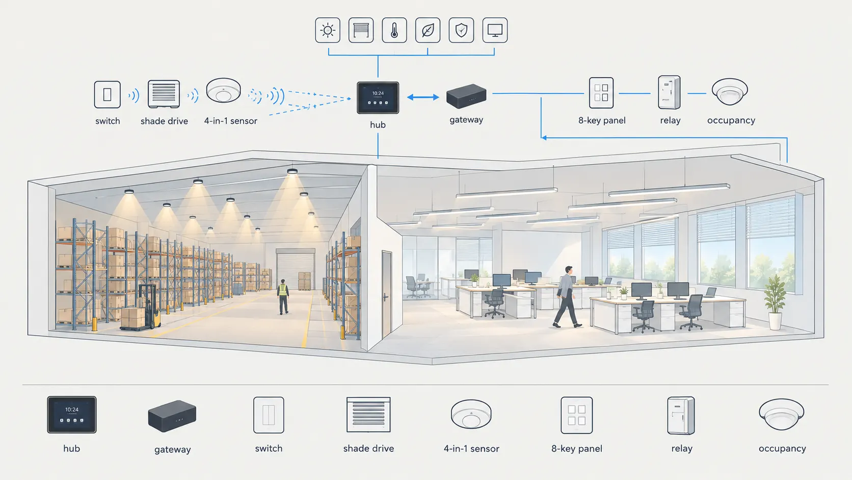
Kept bus on one side, Zigbee shades and sensing on the other — hub exports both to six platforms.
How the Bridge Combination Works
Kept bus on one side, radio mesh on the other, hub above both
Hub and Platform Layer
The 4-inch hub commissions the Zigbee side locally, stores groups, scenes and automations, and exposes the child devices through its Matter Bridge toward HomeKit, Alexa, Google Home, Homey, Home Assistant and SmartThings.
Two-Way Translation
The bridge unit moves commands plus status feedback between protocols: Zigbee switches, shades and environmental readings reach the wired fittings, while wired panel presses and occupancy signals trigger shade positions and routines on the radio side.
Kept Bus Layer
Installed fixtures and their wiring remain in place: an 8-key wired panel, a four-channel relay for non-dimmable loads and a fixture-integrated occupancy-plus-daylight input keep serving the bus they were built for.
System Topology
Platforms above, hub and bridge in the middle, two device families below
Platforms enter over the bridge export; the gateway pair keeps both device families mutually addressable.
Each refurbishment keeps mains and bus wiring as built. Platform commands land on the hub through the Matter Bridge export, the hub drives the radio mesh, and the gateway unit translates toward the wired bus — with status travelling back the same path. Commissioning data lives on the hub and inside the addressed bus devices, so daily operation continues when phones and clouds are absent.
Our supply scope is the visible half — FORT-series high-bay and TRON-series linear housings below. Bridge gear follows openly numbered Sunricher hub, gateway, panel, switch, shade, sensing and relay parts, so replacements stay sourced on the open market instead of locked to one fixture vendor. The vendor card names its phone tool for bus addressing; we repeat that claim as stated without endorsing the app itself.

Scene: warehouse aisle. FORT-A high bays stay on the kept bus while radio shades and sensing join around them.
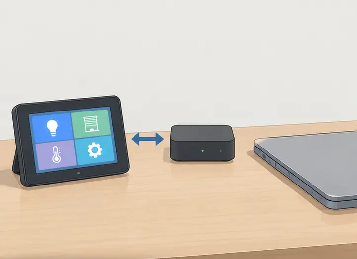
Pair: hub plus gateway. The 4-inch hub holds scenes while the two-way unit translates commands and status both ways.
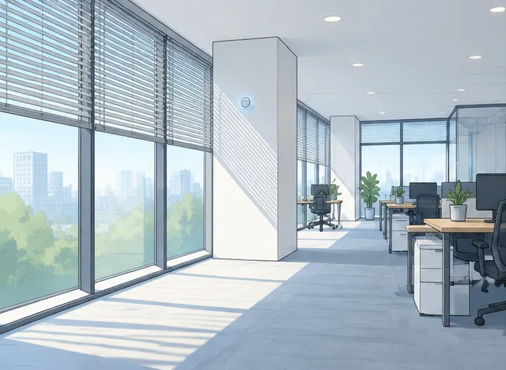
Radio side: shades plus air. Blind drives and 4-in-1 environmental sensing join over the mesh with no new control cable.
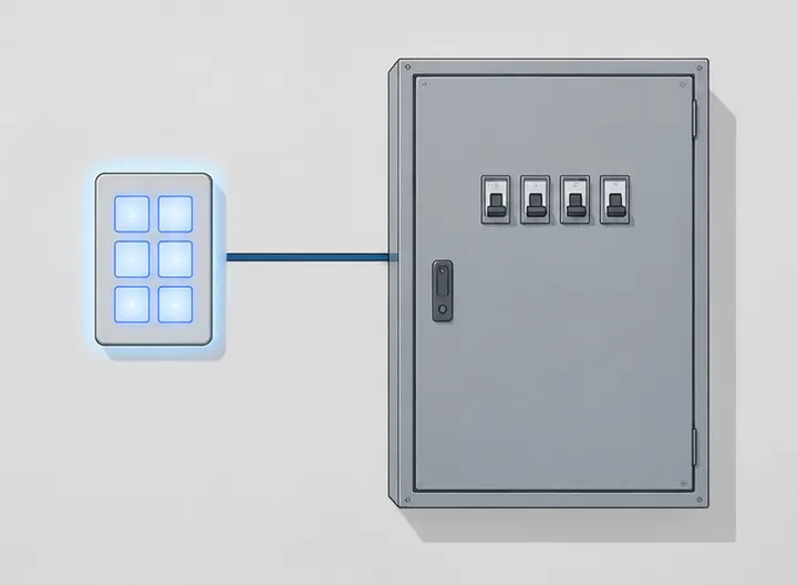
Wired side: panel plus relay. The 8-key panel and four-channel relay keep local hand control on the bus itself.
What Goes Into One Mixed Building
One bridge pair plus openly sourced companion gear
| Part | Role in this solution | Key facts | Supplied by |
|---|---|---|---|
| SR-GW-ZG-LCD4 hub | 4-inch local controller and platform export | Zigbee commissioning with local control; Matter Bridge exposes child devices; groups, scenes and automations stored on the hub | Bridge control gear |
| SR-GW-Z2D-2421 gateway | Bidirectional protocol translator | Zigbee commands reach the bus and bus inputs reach Zigbee in reverse; covers DT6, DT7 and DT8 plus input devices with energy, status and diagnostic data | Bridge control gear |
| SR-2422K8-DA2-WSK panel | Wired 8-key scene input | Eight programmable buttons with feedback LEDs; bus-powered universal wall frame | Bridge control gear |
| SR-ZGP2801K4-FOS switch | Battery-free radio key | Four-button press-powered switch needing neither batteries nor control wiring; short-press, double-click and long-press events per button | Bridge control gear |
| SR-ZG9081A shade drive | Blind and curtain control | Open, close, stop and position control for curtain, roller and venetian motors with scene integration | Bridge control gear |
| SR-ZG9032A-4IN1 sensor | Radio environmental input | Occupancy, temperature, humidity and illuminance sensing with automation and low-battery reporting | Bridge control gear |
| SR-2701DIN-DT7 relay | Wired switching for plain loads | Four normally-open relay outputs for non-dimmable loads; rail mounting on 100–240VAC supply | Bridge control gear |
| SR-DA9032A-PIR sensor | Wired occupancy and daylight input | Fixture-integrated occupancy plus 0–1000 lux daylight measurement for a half-inch luminaire knockout | Bridge control gear |
Model numbers above follow the specialty card for traceability and appear once on this page; all hub, gateway, panel, switch, shade, sensing and relay parts are Sunricher bridge control gear and the body text uses generic names. Device-type coverage spans DT6, DT7 and DT8 color capabilities plus input devices per the DALI Alliance specification library. Below are Teclux housings staying on their own bus drivers — housing and optics per series sheet.
| Teclux housing (series) | Zone | Light task | Bus match |
|---|---|---|---|
| FORT-series linear high-bay housings | Warehouse aisles and bulk storage | High-output general light over racking at commissioned maintained levels | Stay on own wired bus driver, protocol per series sheet |
| TRON-series linear housings | Large open offices | Continuous general light with selectable current per run length | Stay on own wired bus driver, current per series sheet |
- Address the kept bus first — the card names its phone tool for addressing, commissioning and scenes; existing fixtures keep their wiring throughout.
- Join the radio devices to the hub — battery-free switch, shade drive and 4-in-1 sensor enter the mesh with groups stored on the hub.
- Pair the gateway and map both directions — forward scenes toward the bus, reverse triggers from panel and occupancy toward shades and routines.
- Export to platforms and walk-test everything — expose child devices over Matter Bridge, then verify panel-to-shade and sensor-to-scene paths per floor.
Mixed-Building Behavior and When to Pick It
Example settings plus bridge-versus-alternative options
Mixed-protocol buildings usually hit the same three problems — the installed bus cannot talk to newly added shades and sensors, ripping the bus out wastes a working installation, and each platform app sees only half the building. A warehouse-plus-office starting point that commissioning engineers adjust on site:
- Kept aisles hold commissioned levels, shades follow daylight — high bays stay on the bus while blind positions track the 4-in-1 illuminance readings
- Wired panel recalls radio scenes and back — the 8-key wall input calls shade plus light moods; the battery-free switch recalls bus scenes in return
- Platforms see one building, not two systems — six ecosystems address bus fittings as Matter child devices with shared groups and automations
Maintained levels follow EN 12464-1 for the respective task areas; values above are commissioning examples, not fixed firmware. For the wider technology choice, read the mixed wired and wireless lighting overview before fixing the architecture. For open floors where no bus exists and ceilings must stay closed, tunable-white retrofit without new wires covers the mesh-only path.
| Option | Best for | Trade-off |
|---|---|---|
| This page bridge pair for kept buses | Mixed buildings adding Zigbee plus platforms to stock DALI | Needs hub plus gateway hardware on site |
| Mesh-only retrofit path | Floors with no bus and closed ceilings | No wired panel fallback on the bus |
| No-master route for small rooms | Single rooms with local panel plus Matter | No whole-floor scenes or shade fleets |
| Gateway-free corridor tiers | Corridors needing sensing with hand override | Single-zone logic, no platform export |
Warehouse general light points to the linear high bays for warehouse aisles; large-office continuous rows point to the selectable-current linear lights for large offices.
FAQ
Quick answers about the bidirectional bridge
Yes, keeping the installed fixtures and their wiring in place is the whole point of this bridge page — the two-way gateway translates between the kept bus and the new radio mesh instead of replacing either side, so panels, relays and sensors remain wired while shades, switches and environmental inputs join over the air without any new control cables.
- Forward scenes travel from the hub toward the bus; reverse triggers travel back.
- One commissioning flow covers both families behind the single gateway pair.
Yes, reverse triggering is what separates this gateway page from one-way converters — a press on the wired 8-key panel or a signal from the wired occupancy input can call blind positions, scene recalls and automation routines on the radio side, with live status reported back so each side always reflects the current state of the other.
- Map panel buttons to shade-plus-light moods per room or floor.
- Let occupancy and daylight inputs trim blinds as well as fittings.
Six platforms connect through the hub Matter Bridge export with groups, scenes and automations configured on the hub side — HomeKit, Alexa, Google Home, Homey, Home Assistant and SmartThings each reach the bus fittings behind the bridge as Matter child devices, so facility and tenant apps share one consistent device list.
- Confirm the preferred platform with the facility team before mapping names.
- Keep one naming scheme across hub, gateway and platform views.
FORT-series linear high-bay housings cover warehouse aisles and TRON-series linear housings cover large open offices on the kept wired bus — both stay on their own bus drivers while radio shades and 4-in-1 sensing join around them, so the visible half of every mixed-building project ships from our own catalogues.
- Match bus driver protocol against each fitting datasheet before ordering.
- Confirm run currents for TRON-WD rows per length at design stage.
Pick the mesh route where no wired bus exists and pick the no-master route where one small room only needs a local panel plus Matter — for open floors needing tunable scenes without new cables see the retrofit path, and for single rooms needing panel-plus-platform simplicity see the no-master page, while this bridge page stays reserved for stock-bus buildings.
- Existing bus plus new shades means this bridge page, not the mesh page.
- Single-room panel jobs skip the hub and gateway hardware entirely.
Send Message
Fill out the form and we will get back to you as soon as possible