 John, Sales ManagerIndustry News
LED Inrush Tripping Breaker: How Many per Circuit
Introduction
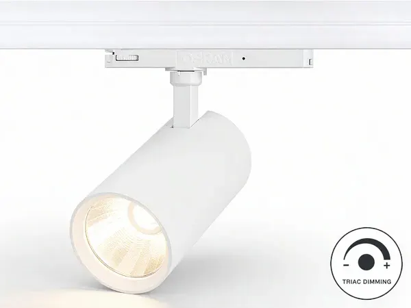
Second night after relamping, 12 added 32 W track heads on the existing B16 tripped at switch-on while the 2016 LEDs on the same board never did. The new heads draw less steady power and a far taller startup surge, so the old headcount no longer holds — this TRIAC track heads with built-in rail driver note shows where the counts below come from and what to ask before adding heads.

Why Steady Watts Lie On Shared Circuits
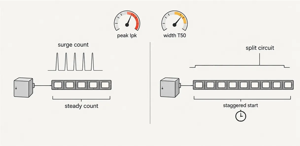
One LED head barely disturbs a board; twenty heads switching together do. Each driver charges its input capacitors at switch-on, and the peaks add up within the same millisecond. Schneider measured 25 56 W luminaires drawing only 1400 W steady yet producing a 237 A surge over 2.5 ms that tripped a 20 A breaker. Two ceilings bind every circuit: the steady-current count and the surge count, and the smaller one governs — on LED circuits it is almost always the surge.
- More heads, same board — second-gen add-ons inherit a breaker sized for calmer loads.
- Short peak, fast trip — the magnetic release reacts in milliseconds, not seconds.
- Cheap drivers pass trouble through — line disturbances become visible flicker downstream.
Fix 1: Count Heads Per Breaker Twice
Size every lighting circuit twice and keep the smaller answer. The steady count divides the breaker rating by per-head current; the surge count divides the breaker surge withstand by driver peak current. Eaton and BEAMA publish the same method: compare the combined pulse against the magnetic-trip band with margin, using driver peak Ipk and pulse width T50 from the driver datasheet.
| Breaker curve | Magnetic trip band | Suits | LED rule |
|---|---|---|---|
| B curve 16 A | 3 to 5 times rated | Resistive rooms | Fewest LED heads; first to trip on surge |
| C curve 16 A | 5 to 10 times rated | Commercial lighting | Default for LED rows; verify Ipk/T50 |
| D curve 16 A | 10 to 20 times rated | Heavy surge plant | Most heads; check cable and selectivity |
| Worked limit | Surge vs steady | 12 32 W heads on B16 | Surge count binds — split circuit or stagger start |
When the surge count binds, split the row across two breakers, sequence the start after outages, or use zero-crossing relays that switch at voltage zero. Never solve tripping by fitting a bigger breaker alone — cable size and short-circuit protection still decide the ceiling.
Worked example — 12 32 W heads on one B16. Figures below are illustrative assumptions showing the Eaton/BEAMA method, not product claims: a 32 W head draws about 0.15 A steady at 230 V, so 12 heads total 1.8 A and pass the steady count on a B16. Against an assumed driver surge of Ipk 40 A with T50 200 microseconds, the combined peak exceeds the B-curve 3 to 5 times band, so the surge count binds near 6 heads. The fix keeps the B16: two circuits of 6, a staggered start, or a zero-crossing relay.
| Count | Maths | 12-head result |
|---|---|---|
| Steady current | 12 heads at about 0.15 A each is 1.8 A at 230 V, inside a B16 | Passes |
| Surge, illustrative Ipk/T50 | Combined peak against the B-curve 3 to 5 times band | Binds near 6 heads |
| Fix that keeps the B16 | Two circuits of 6, staggered start, or zero-crossing relay | 12 heads, no trip |
Swap the assumed 40 A and 200 microseconds for the Ipk/T50 printed on the driver sheet to repeat this for any head. Where the sheet prints no surge line at all, treat the row as unverified and halve the circuit first. For the broader dimming-technology choice on central schedules, the dimming technology choice guide for central schedules compares phase-cut against bus systems while this guide counts heads per breaker.
Fix 2: Match The Wall Dimmer To New Drivers
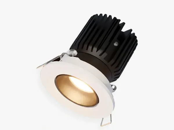
Old leading-edge wall dimmers chop the front of each half-cycle with a hard voltage jump; new capacitive LED drivers prefer the gentle rear chop of trailing-edge dimmers. The wrong pairing flickers worst below 30 percent, buzzes, narrows the range, and wears the driver — a fifteen-minute swap to a trailing-edge LED dimmer cures most cases. The recessed TRIAC spotlight for both dimmer edges dims off leading- and trailing-edge walls across 5 to 35 W heads, so boutiques keep existing wiring while jewelry counters keep low-end glow.
| Pairing | Minimum load | Low-end behaviour | Fix |
|---|---|---|---|
| Leading-edge wall plus new LED drivers | 20 to 50 W per channel | Flicker and buzz below 30 percent | Swap wall to trailing-edge LED type |
| Trailing-edge wall plus LED drivers | 5 to 10 W per channel | Smooth low glow, less EMI | Keep; verify against driver list |
| Flicker metric gate | Pst LM at most 1.0 | SVM at most 0.4 per EU Ecodesign | No datasheet line, no dimmed order |
| Both-edge heads SP01 and VUE-T | Down to 5 W per channel on listed walls | Low glow holds with no rewiring | Keep the existing wall where listed |
Trailing-edge LED walls from mainstream wiring-accessory makers, Lutron and Legrand classes are the common references, suit capacitive drivers best; no link needed here because the choice is verified against the driver sheet, not against a catalogue page. Where the wall must stay, pick heads explicitly listed for both edges and re-test the full row at 10 percent.
Demand the dimmer compatibility list with the driver datasheet and test the full row at 10 percent before sign-off. The retail lighting system with accent and ambient layers assigns dimmed focal points to track and spots while linears carry background light, so one bad dimmer cannot drag the whole sales floor.
Fix 3: Read The Driver Heat Table
Drivers die first at the capacitor, not the LED. Aluminium electrolytic life roughly halves with each 10 degrees of rise, so a room-air table ends where a 60-degree fitting begins. Lutron's 2025 retrofit paper warns that lesser drivers pass normal line disturbances straight through as flicker or shimmer — the same cheap stage that flickers also fails early. Measure air at the housing through a full shift; floors read 15 to 25 degrees cooler than the fitting.
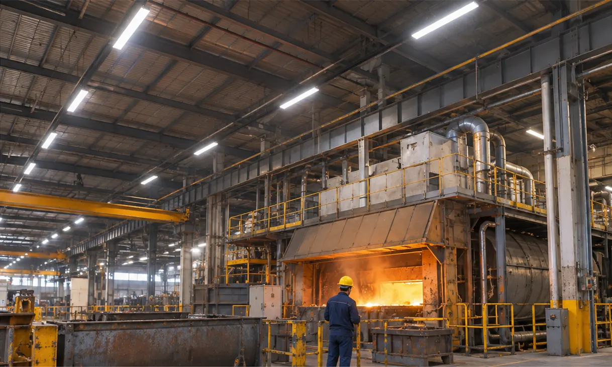
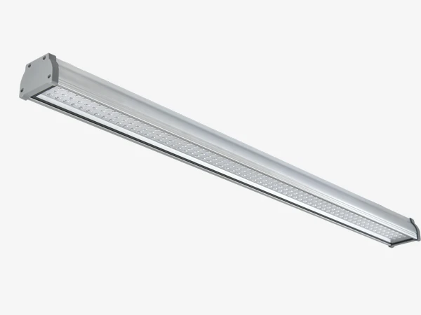
Two poles need opposite care: cold cabinets grow condensation on electronics while furnace bays bake them. The FORT-A-HT high-temperature linear pairs its proven housing with a Tridonic INDUSTRY driver rated minus 40 to plus 80 degrees ambient and life quoted at 60 degrees, holding DALI-2 dimming and D4i data through the hottest shift.
| Sheet row | Complete, FORT-A-HT published | Thin sheet |
|---|---|---|
| Rated ambient | Minus 40 to plus 80 degrees | 25 degrees only |
| Life point | Up to 100,000 hours at 60 degrees, 8-year driver class | 50,000 hours with no temperature |
| Surge | 4 kV built-in plus SPD path toward 10 kV | No surge line |
| Order rule | Hot bays past 60 degrees at the housing | Cool rooms only |
Read any heat claim against those four rows before signing. The phased relamping plan without closing aisles sequences night-by-night swaps while this guide stops the callbacks each swap can trigger.
What To Specify Before Adding Heads
- Surge pair — driver peak Ipk in amps plus pulse width T50 in microseconds for the exact head.
- Breaker line — curve B/C/D plus rating plus which count binds, surge or steady.
- Dimmer list — named compatible walls by edge type with minimum load per channel.
- Flicker gate — Pst LM and SVM figures on the driver sheet, not adjectives.
- Heat rows — rated ta, tc point and hours at 60 degrees at your drive current; no table, no hot-room order.
- Callback maths — one avoided $150 to $500 revisit pays the compatibility check on every row.
| Revisit cost | Typical range | What it burns |
|---|---|---|
| Diagnostic truck roll | $150 to $200 | One fault, one ladder, no fix yet |
| Access equipment day | $150 to $300 | Lift hire where ceilings run high |
| Dimmer swap-back and re-test | $100 to $200 | Wall change plus 10 percent re-test |
| One revisit, all-in | $150 to $500 | Region-dependent; prevention costs less |
FAQ
Conclusion
Count surge before hanging heads: steady count and surge count per breaker, trailing-edge walls for new drivers, heat tables for hot air. Twelve 32 W heads belong on paper twice before they belong on one B16; a fifteen-minute dimmer swap beats a season of flicker; a ta/tc row beats any heat adjective. We publish standard Ipk/T50 and dimmer lists on request — no rows, no order.
A whole system of LED loads sharing a circuit shows cumulative surge effects that a single luminaire never shows.
Sources
- Eaton's LED luminaire and miniature circuit breaker selection guide gives the B/C/D trip bands and the two-count method used above.
- The Schneider Electric LED lamps choice of circuit breaker wiki tables heads per breaker rating with the 237 A field case.
- Lutron's TLED retrofit scenarios technical paper documents pass-through flicker and NEMA 410 control stress on LED rows.
WHY BUYERS WORK WITH LOW CARBON TECLUX
About Low Carbon Teclux
Low Carbon Teclux Co., Ltd. has manufactured LED commercial lighting since 2010. As a factory-direct OEM/ODM manufacturer, we serve importers and distributors across Europe and Australia — from product selection and sample testing to mass production and delivery, one team covers engineering, manufacturing and sales.
Our Engineering Support
We help project buyers select the right fitting, optic and driver — not just compare prices. Send us your application, mounting height, target lux, dimming protocol and finish requirement, and our engineers will recommend a series, optic, driver basis and spare-parts plan for your RFQ. Where no standard fitting fits, we co-develop custom luminaires around your project — housing, optic, driver and finish engineered to your spec, from prototype to mass production.
REQUEST A QUOTECOMPANY PROFILE // DATA_SHEET
NAME
Low Carbon Teclux Co., Ltd.
BRAND NAME
Low-Carbon
BUSINESS TYPE
LED Lighting Manufacturer
SERVICE
Factory Direct / OEM / ODM
MAIN PRODUCTS
LED Track Lights, Linear Lights, Downlights, Outdoor Luminaires
CAPABILITY
Engineering, Manufacturing & Sales in One Team; Sample to Mass Production
CERTIFICATIONS
CE / FCC / RoHS / ISO9001
EXPORT REACH
Europe & Australia
Contents Table
Need Help Selecting the Right Luminaire?
Tell us your application, mounting height and target lux — our engineers will recommend a fitting, optic and driver configuration, or co-develop a custom fitting when no standard model fits.
REQUEST A QUOTESend Message
Fill out the form and we will get back to you as soon as possible